We use cookies to help you navigate efficiently and perform certain functions. You will find detailed information about all cookies under each consent category below.
The cookies that are categorised as "Necessary" are stored on your browser as they are essential for enabling the basic functionalities of the site....
For more information on how Google's third-party cookies operate and handle your data, see: Google Privacy Policy
Necessary cookies are required to enable the basic features of this site, such as providing secure log-in or adjusting your consent preferences. These cookies do not store any personally identifiable data.
Functional cookies help perform certain functionalities like sharing the content of the website on social media platforms, collecting feedback, and other third-party features.
Analytical cookies are used to understand how visitors interact with the website. These cookies help provide information on metrics such as the number of visitors, bounce rate, traffic source, etc.
Performance cookies are used to understand and analyse the key performance indexes of the website which helps in delivering a better user experience for the visitors.
Advertisement cookies are used to provide visitors with customised advertisements based on the pages you visited previously and to analyse the effectiveness of the ad campaigns.
Other uncategorised cookies are those that are being analysed and have not been classified into a category as yet.
Understanding what PWM is, where it is found and how it can be controlled with Rotalink’s absolute or incremental encoders.
Pulse Width Modulation (PWM) is a method of reducing the average power delivered by an electrical signal by effectively breaking up the pulse into discrete parts. The main components of PWM are:
Duty Cycle: The percentage that a signal is active across a set period of time. A 50% duty cycle is on an active signal for half the time and off for the other half.
Frequency: The rate at which the PWM signal repeats itself.
By varying the width of the pulses to control the amount of power supplied to a device. As an example of this, for a PWM with a frequency of 1kHz and a 50% duty cycle, the signal will be active for 0.5 milliseconds and inactive for 0.5 milliseconds for each cycle. Changing the duty cycle allows you to control the power that is delivered.
Found in many everyday items that you wouldn’t even think about. Here are just a few applications:
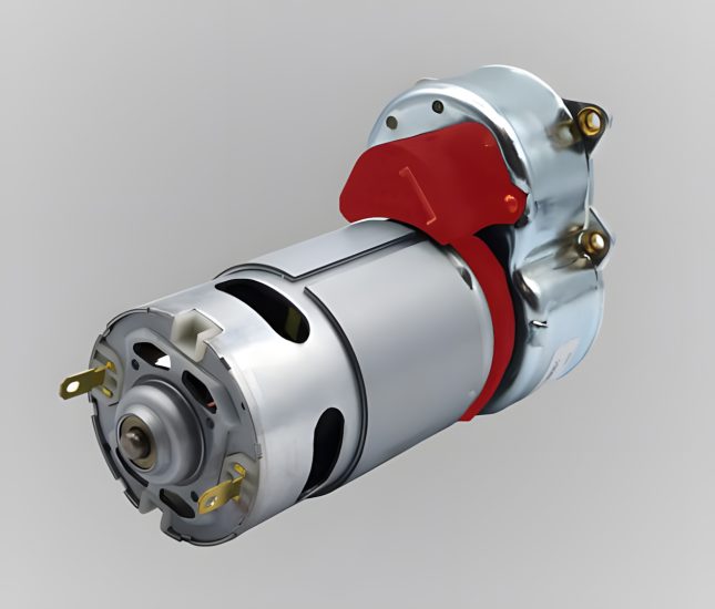
Motor Control: PWM can be used to control the speed of a DC motor by varying the duty cycle.
LED Dimming: PWM is used to control the brightness of LED lights, simply by adjusting the duty cycle you can change the average current going through the LEDs.
Power Delivery: In power supplies, you will find a PWM is used to regulate the voltage and current outputs.
Yes, Pulse Width Modulation signals can be controlled using feedback from Absolute Encoders and Incremental Encoders.
An Absolute Encoder provides a unique digital code that is used for each position of the encoder shaft, allowing for precise positioning readouts. Here’s how an Absolute Encoders being used for PWM works:
An Incremental Encoder provides a service of pulses when the encoder shaft rotates, enabling you to know when the position changes relative to the starting point. This system is most commonly used for speed and position feedback in a closed-loop system. Here’s how Incremental Encoders work with PWM:
By integrating either type of encoder, you will be able to achieve precise control of PWM signals. All coming together to provide better performance and reliability of your motor control system.